1-12
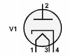
Figure 1-10.—Identification of tube elements.
Now, to use the information in the symbol, you need to know the system used to number tube pins
and socket connections.
Figure 1-11 shows five common pin configurations as viewed from the bottom of each tube or
socket. This is important. In every case, pins and pin connections on sockets are numbered in a clockwise
direction—WHEN VIEWED FROM THE BOTTOM.
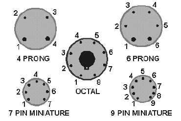
Figure 1-11.—Pin Identification; all tubes are viewed from the bottom.
In each of the five pictures in figure 1-11, there is an easily identified point from which to start
numbering. In the 4-prong and 6-prong tubes, the point is between the two larger prongs. In the octal tube,
the point is directly down from the keyway in the center of the tube. In the 7-pin and 9-pin miniatures, the
point is identified by the larger distance between pins.
Q9.
Name two functions of the base of a vacuum tube.
The Envelope
The envelope of a tube may be made of ceramic, metal, or glass. Its major purpose is to keep the
vacuum in and the atmosphere out. The main reason for this is that the heated filament would burn up in
the atmosphere. There are other reasons for providing a vacuum, but the important thing is to realize that
a tube with a leaky envelope will not function properly.