1-16
You can see from the analysis that the most consistent control of plate current takes place over the
linear portion of the Ep - Ip curve. In most applications, electron tubes are operated in this linear portion of
the characteristic curve.
Plate Resistance (Rp)
One tube parameter that can be calculated from values on the Ep - Ip curve is known as plate
resistance, abbreviated as Rp. In a properly designed electron tube, there is no physical resistor between
cathode and plate; that is, the electrons do not pass through a resistor in arriving at the plate. You may
have wondered, however, why the variable dc voltage source of figure 1-12 didn’t blow a fuse. Doesn’t
the plate circuit appear to be a short circuit-a circuit without a load to limit the current?
The fact is, there is a very real, effective RESISTANCE between cathode and plate. It is not lumped
in a resistor, but the circuit may be analyzed as if it is. The plate resistance of a given tube, Rp, can be
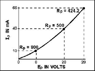
calculated by applying Ohm’s law to the values of Ep and Ip. Figure 1-14 is a typical diode Ep - Ip curve.
The plate resistance has been figured for Rp under three different conditions, as follows:
Figure 1-14.—The Ep - I
characteristic curve for a diode.
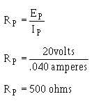
Remember that 1 mA = .001 ampere; therefore 40 mA =.040 ampere.
Solution:
The other two indicated values of Rp were figured in the same way.


