1-21
was a variation in plate current of 7.5 milliamperes. Instead of amplification, De Forest had obtained
"conversion," or in other words, converted a signal voltage to a current variation. This wasn’t exactly what
he had in mind. As it stood, the circuit wasn’t very useful. Obviously, something was needed. After
examining the circuit, De Forest discovered the answer—Ohm's law. Remember E = I × R? De Forest
wanted a voltage change, not a current change. The answer was simple:
In other words, run the plate current variation (caused by the voltage on the grid) through a resistor,
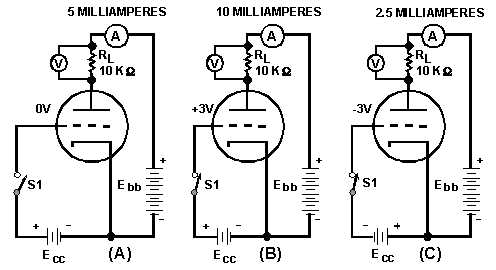
and cause a varying voltage drop across the resistor. This is shown in figure 1-16.
Figure 1-16.—Operation of the plate load resistor.
The circuit is identical to the one in figure 1-15 except that now a resistor (called a plate-load
resistor, RL) has been added to the plate circuit, and a voltmeter has been added to measure the voltage
drop across RL.
In view (A) of figure 1-16, the control grid is at 0 volts. Once again 5 milliamperes flow in the plate
circuit. Now, the 5 milliamperes must flow through RL. The voltage drop is equal to:
E = I × R
E = (5 × 10⁻³ amperes) × (10 × 103 ohms)
E = (5 × 10-3) × (10 × 10
3)
E = 5 × 10
E = 50 volts
Thus the voltage drop across the plate-load resistor, RL, is 50 volts when no voltage is applied to the
grid. In view (B) of the figure, +3 volts is applied to the control grid. Once again plate current increases to
10 milliamperes. The voltage drop across RL is