1-23
Most amplifier circuits are designed to operate with the grid NEGATIVE relative to the cathode.
The voltage that causes this is called a BIAS VOLTAGE. The symbol for the bias supply is Ecc. One
effect of bias (there are several other very important ones) is to reduce or eliminate grid current. Let’s see
how it works.
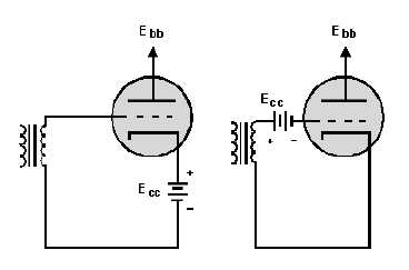
GRID BIAS is a steady, direct voltage that is placed at some point in the external circuit between the
grid and the cathode. It may be in the cathode leg or the grid leg as shown in figure 1-17. It is always in
series with the input signal voltage. In each of the circuits in figure 1-17, Ecc makes the grid negative with
respect to the cathode because of the negative terminal being connected toward the grid and the positive
terminal being connected toward the cathode. With identical components, each circuit would provide the
same bias.
Figure 1-17.—Basic biasing of a triode.
Battery bias is practically never used in modern circuits. Because of its simplicity, however, we will
use it in analyzing the effects of bias. We will present other, more practical methods later.
Let’s assume that the bias voltage in figure 1-17 is -6 volts. Let’s also assume that the peak-to-peak
signal voltage from the transformer is 6 volts. Each of these voltage waveforms is shown in figure 1-18.
From past experience you know that voltages in series ADD. Figure 1-18 has a table of the instantaneous
values of the two voltages added together. The waveforms are drawn from these values.


