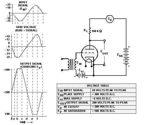
1-28
complexity has to do with DISTORTION. Distortion occurs in a tube circuit any time the output
waveform is not a faithful reproduction of the input waveform.
Polarity inversion and voltage gain of the output waveform are not included in this definition of
distortion. Some circuits are designed to distort the output. The reason and methods for this deliberate
distortion will be covered in a later NEETS module. For the most part, however, we desire that circuits
eliminate or reduce distortion.
Because the grid is close to the cathode, small changes in grid voltage have large effects on the
conduction of triodes. If a large enough input signal is placed on the grid, a triode may be driven into
either plate-current cutoff or plate-current saturation. When this occurs, the tube is said to be
OVERDRIVEN. Overdriving is considered to be a form of DISTORTION.
Look at time zero (0) in the waveforms of figure 1-20. The input signal (Ein) is at zero volts. Grid
voltage equals the bias voltage (-6 volts), and one milliampere of current is flowing through the tube
(quiescent state). Plate voltage (Ep) is 200 volts.
Figure 1-20.—Overdriven triode.
On the negative half of the input signal, the grid voltage is made more negative. This reduces plate
current which, in turn, reduces the voltage drop across RL. The voltage between cathode and the plate is
thereby increased. You can see these relationships by following time "a" through the three waveforms.


