1-32
conduction on the negative half-cycle decreases the gain of that half-cycle. The overall effect of allowing
cathode biasing to follow the input signal is to decrease the gain of the circuit with ac inputs.
This problem can be overcome by installing Ck. The purpose of Ck is to maintain the cathode bias
voltage at a constant level. In common usage, the action of Ck is referred to as "bypassing the ac signal to
ground."
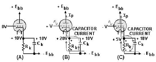
The action of Ck will be explained using figure 1-23. View A shows the circuit under quiescent
conditions. With some conduction through the tube, the cathode and the tops of R
k
and Ck are at +10
volts.
Figure 1-23.—Effect of the bypass capacitor.
In view B, the positive-going signal is applied to the grid. This causes increased conduction through
the tube, which attempts to drive the cathode to +20 volts. But notice that the top of Ck is still at +10 volts
(remember capacitors oppose a change in voltage). The top plate of Ck is, in effect, 10 volts negative in
relation to the top of Rk. The only way that Ck can follow the signal on the top of Rk (+20 volts) is to
charge through the tube back to the source, from the source to the lower plate of Ck. When Ck charges
through the tube, it acts as the source of current for the cathode. This causes the cathode to remain at +10
volts while the capacitor is charging.
View C of the figure shows the same signal. Under these conditions, conduction through Rk will
decrease. This will cause a decrease in current flow through Rk. Decreased current means decreased
voltage drop. The top of Rk will try to go to +5 volts. Ck must now go more negative to follow the top of
Rk. To do this, current must flow from Ck through Rk, to the top plate of Ck. This discharging of Ck will
increase current flow through Rk and increase the voltage drop across Rk, forcing the top to go more
positive. Remember, the voltage drop is due to current flow through the resistor. (The resistor could care
less if the current is caused by conduction or capacitor action.) Thus, the cathode stays at +10 volts
throughout the capacitor-charge cycle.
There is one point that we should make. Ck and Rk are in parallel. You learned from previous study
that voltage in a parallel circuit is constant. Thus, it would seem impossible to have the top of Rk at one
voltage while the top plate of Ck is at another. Remember, in electronics nothing happens instantaneously.
There is always some time lag that may be measured in millionths or billionths of seconds. The action of
Ck and Rk that was just described takes place within this time lag. To clarify the explanation, the voltages
used at the components Rk and Ck were exaggerated. Long before a 10-volt differential could exist
between the tops of Rk and Ck, Ck will act to eliminate this voltage differential.


