1-27
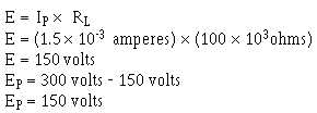
cathode, through the grid, to the plate. Assume that the plate current in this case will increase to 1.5
milliamperes. This will cause plate voltage (Eb) to decrease to 150 volts as shown below.
This is shown on the output waveform at time c.
At time d, the input signal voltage decreases back to zero volts. The grid will return to the quiescent
state of -6 volts, and conduction through the tube will again be at 1 milliampere. The plate will return to
its quiescent voltage of +200 volts (shown at time d on the output waveform).
As you can see, varying the grid by only 6 volts has caused the output of the triode to vary by 100
volts. The input signal voltage has been amplified (or increased) by a factor of 16.6. This factor is an
expression of amplifier VOLTAGE GAIN and is calculated by dividing the output signal voltage by the
input signal voltage.
Before going on to the next section, there is one more thing of which you should be aware. Look
again at the waveforms of figure 1-19. Notice that the output voltage of the amplifier is 180º out of phase
with the input voltage. You will find that this polarity inversion is a characteristic of any amplifier in
which the output is taken between the cathode and the plate. This is normal and should not confuse you
when you troubleshoot or work with this type of circuit.
Q16.
Why is the control grid of a triode amplifier negatively biased?
Q17.
For a circuit to be considered to be in the quiescent condition, what normal operating voltage
must be zero?
Q18.
A triode amplifier similar to the one shown in figure 1-19 has an Ebb -350 volts dc. The plate-
load resistor is 50 N
8QGHU TXLHVFHQW FRQGLWLRQV PLOOLDPSHUHV RI FXUUHQW FRQGXFWV
through the tube. What will be the plate voltage (Ep) under quiescent conditions?
Q19.
A 2-volt, peak-to-peak, ac input signal is applied to the input of the circuit described in Q18.
When the signal is at its maximum positive value, 2.5 milliamperes flows through the tube.
When the input is at its maximum negative value, conduction through the tube decreases to .5
milliamperes.
a. What is the peak-to-peak voltage of the output signal?
b. What is the phase relationship between the input and output signals?
FACTORS AFFECTING TRIODE OPERATION
The triode circuit you have just studied is a fairly simple affair. In actual application, triode circuits
are a bit more complex. There are two reasons for this. The first has to do with the triodes ability to
amplify and perform other functions. Triodes come in many different types. Each of these types has
different internal characteristics and different capabilities. Because of this, each triode circuit must be
designed to accommodate the triodes special characteristics. The second reason for the increase in


