3-13
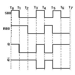
Figure 3-13. —R-S flip-flop with inverted inputs timing diagram.
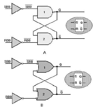
Figure 3-14 shows two methods of constructing an R-S FF. We can use these diagrams to prove the
Truth Table for the R-S FF.
Figure 3-14. —R-S FF construction: A. Using cross-coupled NAND gates; B. Using cross-coupled OR gates.


