3-21
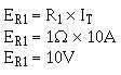
The voltage drop across R1 can be computed:
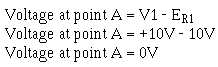
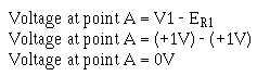
The voltage at point A would be equal to the voltage of V1 minus the voltage drop of R1.
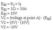
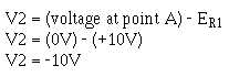
To check this result, compute the voltage drop across R2 and subtract this from the voltage at point
A. The result should be the voltage of V2.
It is not necessary that the voltage supplies be equal to create a point of virtual ground. In view (B)
V1 supplies +1 volt to the circuit while V2 supplies -10 volts. The total difference in potential is 11 volts.
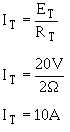
The total resistance of this circuit (R1 + R2) is 11 ohms. The total current (IT) is 1 ampere. The voltage
drop across R1 (ER1 = R1 I
T) is 1 volt. The voltage drop across R2 (ER2 = R2 I
T) is 10 volts. The
voltage at point A can be computed:
So point A is at virtual ground in this circuit also. To check the results, compute the voltage at V2.