3-16
1. Very high gain
2. Very high input impedance
3. Very low output impedance
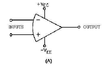
Figure 3-10A.—Schematic symbols of an operational amplifier.
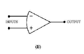
Figure 3-10B.—Schematic symbols of an operational amplifier.
Since no single amplifier stage can provide all these characteristics well enough to be considered an
operational amplifier, various amplifier stages are connected together. The total circuit made up of these
individual stages is called an operational amplifier. This circuit (the operational amplifier) can be made up
of individual components (transistors, resistors, capacitors, etc.), but the most common form of the
operational amplifier is an integrated circuit. The integrated circuit (chip) will contain the various stages
of the operational amplifier and can be treated and used as if it were a single stage.
BLOCK DIAGRAM OF AN OPERATIONAL AMPLIFIER
Figure 3-11 is a block diagram of an operational amplifier. Notice that there are three stages within
the operational amplifier.