3-18
Q-16.
What is the most commonly used form of the operational amplifier?
Q-17.
Draw the schematic symbol for an operational amplifier.
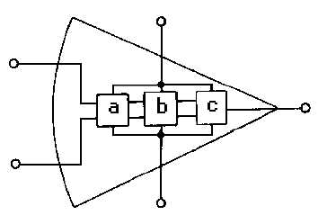
Q-18.
Label the parts of the operational amplifier shown in figure 3-12.
Figure 3-12.—Operational amplifier.
CLOSED-LOOP OPERATION OF AN OPERATIONAL AMPLIFIER
Operational amplifiers can have either a closed-loop operation or an open-loop operation. The
operation (closed-loop or open-loop) is determined by whether or not feedback is used. Without feedback
the operational amplifier has an open-loop operation. This open-loop operation is practical only when the
operational amplifier is used as a comparator (a circuit which compares two input signals or compares an
input signal to some fixed level of voltage). As an amplifier, the open-loop operation is not practical
because the very high gain of the operational amplifier creates poor stability. (Noise and other unwanted
signals are amplified so much in open-loop operation that the operational amplifier is usually not used in
this way.) Therefore, most operational amplifiers are used with feedback (closed-loop operation).
Operational amplifiers are used with degenerative (or negative) feedback which reduces the gain of
the operational amplifier but greatly increases the stability of the circuit. In the closed-loop configuration,
the output signal is applied back to one of the input terminals. This feedback is always degenerative
(negative). In other words, the feedback signal always opposes the effects of the original input signal. One
result of degenerative feedback is that the inverting and noninverting inputs to the operational amplifier
will be kept at the same potential.
Closed-loop circuits can be of the inverting configuration or noninverting configuration. Since the
inverting configuration is used more often than the noninverting configuration, the inverting configuration
will be shown first.
Inverting Configuration
Figure 3-13 shows an operational amplifier in a closed-loop, inverting configuration. Resistor R2 is
used to feed part of the output signal back to the input of the operational amplifier.