3-26
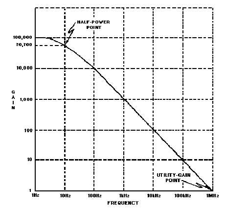
configuration. The UNITY GAIN POINT, where the signal out will have the same amplitude as the signal
in (the point at which the gain of the amplifier is 1), is 1 megahertz for the amplifier. As you can see, the
frequency response of this amplifier drops off quite rapidly.
Figure 3-17.—Open-loop frequency-response curve.
Figure 3-17 is the open-loop frequency-response curve. You have been told that most operational
amplifiers are used in a closed-loop configuration. When you look at the frequency-response curve for a
closed-loop configuration, one of the most interesting and important aspects of the operational amplifier
becomes apparent: The use of degenerative feedback increases the bandwidth of an operational amplifier
circuit.
This phenomenon is another example of the difference between the operational amplifier itself and
the operational-amplifier circuit (which includes the components in addition to the operational amplifier).
You should also be able to see that the external resistors not only affect the gain of the circuit, but the
bandwidth as well.
You might wonder exactly how the gain and bandwidth of a closed-loop, operational-amplifier
circuit are related. Figure 3-18 should help to show you the relationship. The frequency-response curve
shown in figure 3-18 is for a circuit in which degenerative feedback has been used to decrease the circuit
gain to 100 (from 100,000 for the operational amplifier). Notice that the half-power point of this curve is
just slightly above 10 kilohertz.