3-25
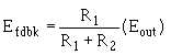
has been dropped by R2. In either case, the feedback signal (Efdbk) is the ratio of R1 to the entire voltage
divider (R1 + R2) multiplied by the output signal (Eout).
Mathematically, the relationship of the output signal, feedback signal, and voltage divider is:
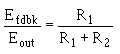
If you divide both sides of the equation by Eout:
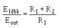
By inverting both sides of the equation:
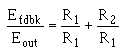
Separating the right-hand side:
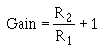
Remember:
Therefore, by substitution:
You can now see that the gain of the noninverting configuration is determined by the resistors. The
formula is different from the one used for the inverting configuration, but the gain is still determined by
the values of R1 and R2.
BANDWIDTH LIMITATIONS
As with most amplifiers, the gain of an operational amplifier varies with frequency. The
specification sheets for operational amplifiers will usually state the open-loop (no feedback) gain for d.c.
(or 0 hertz). At higher frequencies, the gain is much lower. In fact, for an operational amplifier, the gain
decreases quite rapidly as frequency increases.
Figure 3-17 shows the open-loop (no feedback) frequency-response curve for a typical operational
amplifier. As you should remember, bandwidth is measured to the half-power points of a frequency-
response curve. The frequency-response curve shows that the bandwidth is only 10 hertz with this