3-15
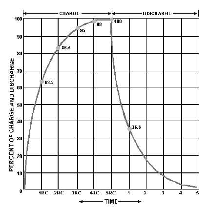
Figure 3-16.—RC time constant chart.
In filter circuits the capacitor is the common element to both the charge and discharge paths.
Therefore, to obtain the longest possible discharge time, you want the capacitor to be as large as possible.
Another way to look at this is: The capacitor acts as a short circuit around the load (as far as the ac
component is concerned), and since
the larger the value of the capacitor (C), the smaller the opposition (XC) or resistance to ac.
Now let's look at inductors and their application in filter circuits. Remember, AN INDUCTOR
OPPOSES ANY CHANGE IN CURRENT. In case you have forgotten, a change in current through an
inductor produces a changing electromagnetic field. The changing field, in turn, cuts the windings of the
wire in the inductor and thereby produces a counterelectromotive force (cemf). It is the cemf that opposes
the change in circuit current. Opposition to a change in current at a given frequency is called inductive
reactance (XL) and is measured in ohms. The inductive reactance (XL) of an inductor is determined by the
applied frequency and the inductance of the inductor. Mathematically,
XL = 2!fL
From the preceding formula, you know that if either frequency or inductance is increased, the XL
will increase. Since inductors are placed in series with the load (fig. 3-17), the larger the XL, the larger the
ac voltage developed across the inductor and the smaller the ac voltage developed across the load.