3-11
Q13. What is the average voltage (Eavg) output of a full-wave rectifier that has an output of 100 volts
peak?
The Bridge Rectifier
When four diodes are connected as shown in figure 3-12, the circuit is called a BRIDGE
RECTIFIER. The input to the circuit is applied to the diagonally opposite corners of the network, and
the output is taken from the remaining two corners.
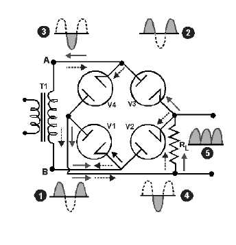
Figure 3-12.—Bridge rectifier circuit.
During one half-cycle of the applied voltage, point A becomes positive with respect to point B by the
amount of voltage induced into the secondary of the transformer. During this time, the voltage between
points A and B may be considered to be impressed across V1, the load resistor RL, and V3, in series. The
voltage applied across these tubes makes their plates more positive than their cathodes, and current flows
from point B through tube V1 in an upward direction across the load resistor, through tube V3, to point A.
This path is indicated by the solid arrows. The waveform is shown as numbers (1) and (2).
One half-cycle later, the polarity across the secondary reverses, making the plates of V1 and V3
negative with respect to their cathodes. At the same time, the plates of V2 and V4 become positive with
respect to their cathodes, and current flows in the direction indicated by the dashed arrows. The current
through RL is always in the same direction. This current, in flowing through RL, develops a voltage
corresponding to that shown in waveform (5) of the figure. The bridge rectifier is a full-wave rectifier
since current flows through the load during both half cycles of the applied alternating voltage.
One advantage of a bridge rectifier over a conventional full-wave rectifier is that with a given
transformer, the bridge rectifier produces a voltage output that is nearly twice that of the conventional
full-wave circuit. We can show this by assigning values to some of the components as shown in figure
3-13, views (A) and (B). Assume that the same transformer is used in both circuits. The peak voltage
developed between points X and Y is 1,000 volts in both circuits. In the conventional full-wave circuit,