3-18
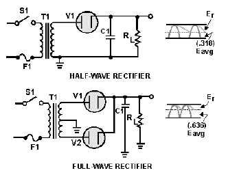
Figure 3-22.—Half-wave/full-wave rectifiers (with capacitor filters).
The value of the capacitor is fairly large (several microfarads); it thus presents a relatively low
reactance to the pulsating current and stores a substantial charge. The rate of charge for the capacitor is
limited only by the relatively low resistance of the conducting diode. The RC charge time of the circuit is,
therefore, relatively short. As a result, when the pulsating voltage is first applied to the circuit, the
capacitor charges rapidly and almost reaches the peak value of the rectified voltage within the first few
cycles. The capacitor attempts to charge to the peak value of the rectified voltage anytime a diode is
conducting, and tends to retain its charge when the rectifier output falls to zero. (The capacitor cannot
discharge immediately). The capacitor slowly discharges through the load resistance (RL) during the time
the rectifier is nonconducting.
The rate of discharge of the capacitor is determined by the value of capacitance and the value of the
load resistance. If the capacitance and load resistance values are large, the RC discharge time for the
circuit is relatively long.
From the waveforms shown in figure 3-22, you should see that the addition of C1 to the circuit
results in an increase in the average value of output voltage (Eavg) and a reduction in the amplitude of the
ripple component (Er) present across the load resistance.
Now, let's consider a complete cycle of operation using a half-wave rectifier, a capacitive filter (C1),
and a load resistor (RL).
As shown in figure 3-23, C1 is assumed to be large enough to ensure a small reactance to the
pulsating rectified current. The resistance of RL is assumed to be much greater than the reactance of C1 at
the input frequency.