3-16
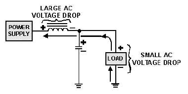
Figure 3-17.—Voltage drops in an inductive filter.
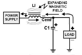
Now back to our circuit. As illustrated in figure 3-18, when the current starts to flow through the
coil, an expanding magnetic field builds up around the inductor. This magnetic field around the coil
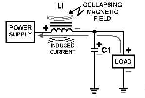
develops the cemf that opposes the change in current. When the rectifier current decreases as shown in
figure 3-19, the magnetic field collapses and again cuts the turns (windings) of wire, thus inducing current
into the coil. This additional current adds to the rectifier current and attempts to keep it at its original
level.
Figure 3-18.—Inductive filter (expanding field).
Figure 3-19.—Inductive filter (collapsing field).
Now that you have learned how the components in the filter circuits react to current flow from the
rectifier, let's discuss the different types of filter circuits in use today.