3-17
Q16. If you increase the value of the capacitor will the XC increase or decrease? Why?
The Capacitor Filter
The simple capacitor filter is the most basic type of power supply filter. The use of this filter is very
limited. It is sometimes used on extremely high-voltage, low-current power supplies for cathode-ray and
similar electron tubes that require very little load current from the supply. This filter is also used in
circuits where the power-supply ripple frequency is not critical and can be relatively high.
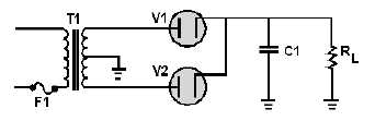
The simple capacitor filter shown in figure 3-20 consists of a single-filter element. This capacitor
(C1) is connected across the output of the rectifier in parallel with the load. The RC charge time of the
filter capacitor (C1) must be short and the RC discharge time must be long to eliminate ripple action when
using this filter. In other words, the capacitor must charge up fast with preferably no discharge at all.
Better filtering also results when the frequency is high; therefore, the full-wave rectifier output is easier to
filter than the half-wave rectifier because of its higher frequency.
Figure 3-20.—Full-wave rectifier with a capacitor filter.
To understand better the effect that filtering has on E
avg, compare the rectifier circuits without filters
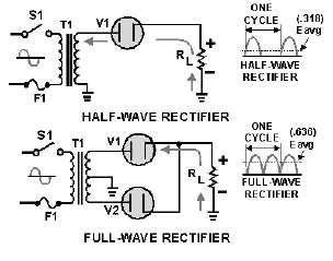
in figure 3-21 to those with filters in figure 3-22. The output waveforms in figure 3-21 represent the
unfiltered outputs of the half-wave and full-wave rectifier circuits. Current pulses flow through the load
resistance (RL) each time a diode conducts. The dashed line indicates the average value of output voltage.
For the half-wave rectifier, Eavg is less than half the peak output voltage (or approximately 0.318 of the
peak output voltage). For the full-wave rectifier, Eavg is approximately 0.637. This value is still much less
than the applied voltage. With no capacitor connected across the output of the rectifier circuit, the
waveform has a large pulsating component (ripple) compared with the average or dc component. Now
refer to figure 3-22. When a capacitor is connected across the output (in parallel with RL), the average
value of output voltage (Eavg) is increased due to the filtering action of capacitor C1.
Figure 3-21.—Half-wave/full-wave rectifiers (without filters).