2-6
Frequency Multiplication
Designing and building a stable crystal oscillator is difficult. As operating frequencies increase, the
crystal must be ground so thin that it often cracks while vibrating. You will find that you can get around
this problem by operating the oscillators in most transmitters at comparatively low frequencies,
sometimes as low as 1/100 (.01) of the output frequency. You raise the oscillator frequency to the
required output frequency by passing it through one or more frequency multipliers. Frequency multipliers
are special power amplifiers that multiply the input frequency. Stages that multiply the frequency by 2 are
called doublers; those that multiply by 3 are triplers; and those multiplying by 4 are quadruplers.
You will find the main difference between low-frequency and high-frequency transmitters is the
number of frequency-multiplying stages used. Figure 2-5 shows the block diagram of the frequency-
multiplying stages of a typical Navy uhf/vhf transmitter. The oscillator in this transmitter is tunable from
18 megahertz to 32 megahertz. You have multiplier stages that increase the oscillator frequency by a
factor of 12 through successive multiplications of 2, 2, and 3.
Figure 2-5.—Frequency multiplying stages of a typical vhf/uhf transmitter.
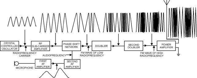
Figure 2-6 is a block diagram of an fm transmitter showing waveforms found at various test points.
In high-power applications you often find one or more intermediate amplifiers added between the second
doubler and the final power amplifier.
Figure 2-6.—Block diagram of an fm transmitter and waveforms.


