2-4
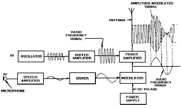
amplifier. The pa combines the rf carrier and the modulating signal in the power amplifier to produce the
amplitude-modulated signal output for transmission. In the absence of a modulating signal, a continuous
rf carrier is radiated by the antenna.
Figure 2-3.—AM radiotelephone transmitter block diagram.
FREQUENCY MODULATED TRANSMITTER
In frequency modulation (fm) the modulating signal combines with the carrier to cause the frequency
of the resultant wave to vary with the instantaneous amplitude of the modulating signal.
Figure 2-4 shows you the block diagram of a frequency-modulated transmitter. The modulating
signal applied to a varicap causes the reactance to vary. The varicap is connected across the tank circuit of
the oscillator. With no modulation, the oscillator generates a steady center frequency. With modulation
applied, the varicap causes the frequency of the oscillator to vary around the center frequency in
accordance with the modulating signal. The oscillator output is then fed to a frequency multiplier to
increase the frequency and then to a power amplifier to increase the amplitude to the desired level for
transmission.

