5-7
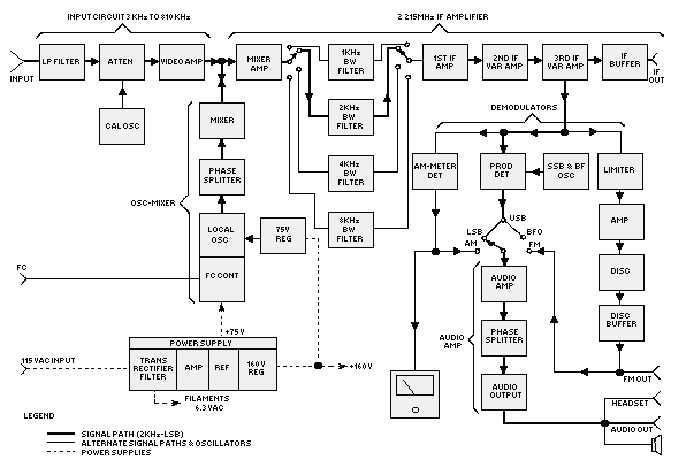
Figure 5-6.—Receiver block diagram.
A Hartley configuration is used for the local oscillator. The oscillator output is equal to the tuned
frequency plus 2.215 megahertz. Two voltage-variable capacitors are used in the local oscillator to
stabilize small frequency variations. A phase splitter is used to drive the mixer diodes into conduction
during half of the local oscillator cycle.
The mixer circuit uses the diodes to heterodyne the input signal with the local oscillator signal from
the phase splitter. The diodes short the signal to ground during half the local oscillator cycle.
The IF amplifier stages consist of the mixer amplifier, four selectable bandwidth filters, three IF
amplifiers, and an IF buffer amplifier.
The output of the mixer is directly coupled to the mixer amplifier. The IF signal is then directed
through one of four bandwidth filters to the first IF amplifier. The signal proceeds to the second and third
IF amplifiers for amplification before demodulation. An IF buffer amplifier is used to pass the IF to the IF
OUT jack and to isolate this jack from the rest of the circuitry.
Three demodulators are used in this receiver. They are the AM detector, product detector, and fm
detector. The AM detector is used to demodulate AM signals. The product detector demodulates ssb, cw,
and fsk signals, and the fm detector demodulates fm signals only. An output from the fm detector is
provided to the FM OUT jack. This fm output may be used for recording or detailed analysis.


