5-6
Receive Equipment
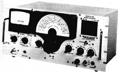
The receiver you will study here is fundamentally the same as those we covered in chapter 2. A
receiver used in this frequency range is about the same electrically as one used in any other range. Figure
5-5 shows the receiver we will discuss. It is a highly sensitive, special purpose receiver because it is
capable of splitting-out multiplex signals for detection and reproduction. This receiver covers the
frequency range of 3 kilohertz to 810 kilohertz in five bands. It will receive most types of signals,
including AM, cw, ssb, fm, and fsk. All operator controls are on the front panel, and a speaker and
headset jack permit monitoring.
Figure 5-5.—Typical vlf to mf receiver.
Our receiver has five basic stages excluding the power supply. With the exception of a video
amplifier in place of an rf amplifier, the circuits perform the functions normally associated with a typical
receiver. Figure 5-6 is a block diagram showing the signal paths of the receiver. The input stage consists
of a low-pass filter, an attenuator, a calibration oscillator, and a video amplifier. The low-pass filter passes
input frequencies below 900 kilohertz. These frequencies are passed to the attenuator, which sets the
signal to the proper level to drive the mixer. This minimizes noise and distortion. The calibration
oscillator produces a 250-kilohertz output. It is used to calibrate the receiver level and to check for tuning
dial accuracy. The input signal is direct-coupled from the attenuator to the video amplifier. This amplifier
is a broadband, constant-impedance driver for the mixer. The oscillator-mixer stage consists of a mixer,
phase splitter, local oscillator, and frequency control circuits.


