5-3
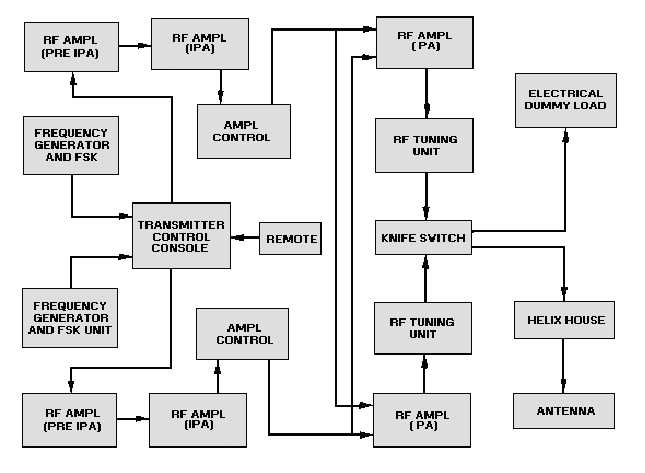
Figure 5-1.—Doubled-up transmitter block diagram.
The frequency generator part of the frequency generator and fsk block is an oscillator. It provides the
carrier frequencies for the cw mode. The fsk part is a FREQUENCY SYNTHESIZER (a frequency source
of high accuracy). It makes both the mark and space frequencies from a very stable clock oscillator. The
keying pulses determine which fsk frequency the keyer chooses to transmit. This signal is then sent to the
transmitter control console where it is distributed to the first rf amplifier. This amplifier is referred to as
the preliminary intermediate-power amplifier (pre-ipa). The pre-ipa uses linear, untuned, push-pull, rf
amplifiers to provide amplified rf to drive other rf amplifiers. The pre-ipa output goes to the intermediate
power amplifier (ipa).
The ipa receives the pre-ipa output, amplifies the signal, and drives other selected power amplifiers.
The ipa is a single-stage, untuned, linear, push-pull, rf circuit that uses water and forced-air cooled tubes.
Signals are then sent through the amplifier control, where they are used for signal monitoring
purposes before being applied to the final rf amplifier (pa). The pa amplifies the signal to the final desired
power level. The pa also contains variometers (variable inductors) for coupling. This coupled output is
fed to the rf tuning unit.
The rf tuning unit consists of variable oil-filled capacitors and a fixed inductor for frequency tuning.
The signal is then sent to a knife switch. This switch simply routes the signal to the DUMMY LOAD or
the antenna by way of the HELIX HOUSE. (A dummy load is a nonradiating device the absorbs the rf


