3-32
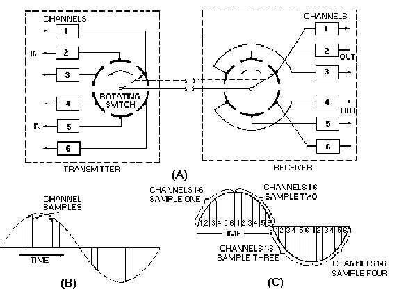
Figure 3-29.—Fundamental principle of time-division multiplexing.
When the transmitter and receiver switches are synchronized, the signals will be fed in the proper
sequence to the receiver channels. The samples from transmitter channel one will be fed to receiver
channel one. In this way, many channels of audio are combined to form a single output (multiplexed)
chain. Time spacing occurs between the components of the separate channels. The chain is transmitted
(via wire or radio path) to distant demultiplexing receivers. Each receiving channel functions to select and
reconstruct only the information included in the originally transmitted channel.
In most present day applications, electronic switching is used as the sampling component. The main
advantage to electronic sampling is the longer life of an electronic switch when compared to an
electromechanical switch. We use a mechanical system in our example to make this concept easier for
you to see.
Now let's look at figure 3-29, view B, where channel one is shown sampled four times. (This is the
output of channel one in our transmitter.) Figure 3-29, view C, shows all six channels being sampled four
times during each cycle. (This is the output of the rotating switch in our transmitter.) What you see here is
a continuous, time-sharing waveform.
More than six channels (perhaps 24 or more) may be used. As we increase the number of channels,
the width of each sample segment must be reduced. The problem with reducing the width of the pulse is
that the bandwidth (bw) necessary for transmission is greatly increased. Decreasing the pulse width
decreases the minimum required rise time of the sampling pulse and increases the required bandwidth.
When you increase the number of channels, you increase the bw. The bw is also affected by the shape of
the sampling pulse and the method used to vary the pulse.


