3-28
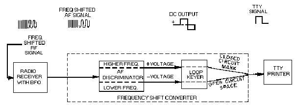
Figure 3-25.—Frequency shift receiving system simplified block diagram.
In diversity operation the comparator section of the converter-comparator group (shown in figure 3-
24) compares the strength of the signals from two receivers. Signals from each converter are fed into a
comparator circuit that compares the signals. This comparison is displayed on a crt on the front of the
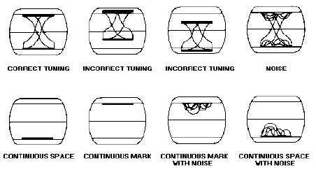
equipment. The comparison is in the form of LISSAJOUS PATTERNS. A lissajous pattern is a
combined, simultaneous display of the amplitude and phase relationships of two input signals. One signal
is applied to the vertical and the other to the horizontal deflection circuits. Lissajous patterns have many
applications in electronics. They have operational uses as well as uses in corrective and preventive
maintenance. Further coverage on lissajous patterns can be found in NEETS, Module 19, The
Technician's Handbook. Figure 3-26 shows several typical lissajous monitoring patterns for the converter-
comparator group. Once we have a correctly tuned signal, the comparator feeds it to the communication
patching panel for patching to the tty. Now let's refer back to figure 3-24 while we discuss the rest of the
units in the system.
Figure 3-26.—Typical lissajous monitoring patterns.
COMMUNICATION PATCH PANEL.—The communication patch panel serves the same
functions on the receive side of the rfcs system as it did on the transmit side. It routes the dc signal to the


