3-27
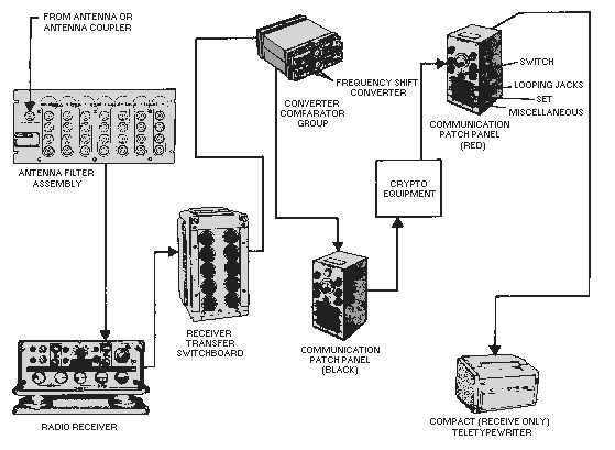
Figure 3-24.—Rfcs receive system.
ANTENNA FILTER ASSEMBLY.—The antenna filter assembly is connected to the antenna and
receives the rf signal from the antenna. It filters out any unwanted rf signals and allows the desired band
of frequencies to pass.
RADIO RECEIVER.—The radio receiver takes the rf signal passed on by the antenna filter and
translates it to an audio signal.
RECEIVER TRANSFER SWITCHBOARD.—The receiver transfer switchboard is used to tie the
receiver to any converter unit connected to it. This allows you a wide selection of equipment for
connection to the same receiver.
CONVERTER-COMPARATOR GROUP.—The converter-comparator group is used with
receivers in either space or frequency diversity operation. When diversity operation is not required, each
converter can be used separately with a single receiver.
Each converter has its own COMPARATOR circuitry. This built-in design feature results in a
considerable reduction in size from older units. The comparator was located in a separate chassis in the
older units. Size has been further reduced through the use of microelectronics.
Figure 3-25 shows the basic method we use to convert a frequency-shift rf signal into a signal that
controls the dc loop of a tty. The frequency shifts of the af output from the receiver are converted into dc
pulses by the af discriminator. The dc pulses are then fed into the keyer. The keyer opens and closes the
dc loop of the tty according to the mark and space characters received.


