3-3
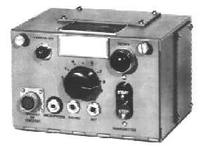
Figure 3-2.—Radio set control unit.
Under standard operating conditions up to four of these units can be used in parallel with a single
transmitter and receiver group to provide additional operating positions. This setup is often found aboard
ship where a transmitter and/or receiver is controlled and operated from several locations such as the
bridge or the combat information center.
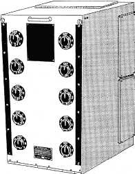
TRANSFER SWITCHBOARDS
A transmitter transfer switchboard provides the capability to transfer remote control station functions
and signals to transmitters. Figure 3-3 is a representative transfer switchboard that provides the capability
for selectively transferring any one, or all, of ten remote control station functions and signals to any one
of six transmitters. The cabinet has ten rotary switches arranged in two vertical rows of five each. Each
switch has eight positions. The circuitry is arranged so that you cannot parallel transmitter control
circuits; that is, you cannot connect more than one transmitter to any remote control location.
Figure 3-3.—Transmitter transfer switchboard.
Each switch operating knob corresponds to a remote control station. Each switch position (1 through
6) corresponds to a transmitter. One switch position, X, provides for transfer of all circuits to additional