3-8
case. An internal fan circulates the nitrogen over and through the heat-producing elements and then
through the air duct. While passing through the air duct, the nitrogen loses its heat to the bottom of the
case. This heat is then transferred by convection through fins on the bottom of the case and by conduction
through the mounting feet.
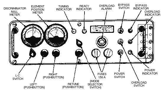
Figure 3-7 shows the antenna coupler control unit. This unit provides the power and control signals
required to tune the coupler. Control signals are either automatically produced by the coupler control
when a tune cycle is initiated or manually produced with the front panel controls.
Figure 3-7.—Antenna coupler control unit.
All dc operating voltages are produced from a 115-volt, 48- to 63- or 350- to 450-hertz, single-phase
primary power source. Meter and protection circuits are used to give you complete control of the coupler
from the remotely positioned coupler control unit.
Q4. If the rf amplifier discussed has an 80 milliwatt input, what would be the maximum output?
Q5. What are the tuning modes for the coupler group discussed?
Q6. What is the purpose of an antenna coupler?
Q7. Why is the coupler pressurized with nitrogen?
RADIO TRANSMITTER.—Figure 3-8 shows the front panel of the radio transmitter unit. The
radio transmitter accepts audio or coded intelligence and uses it to modulate one of 280,000 possible
operating radio frequencies in the 2.0- to 29.999-megahertz frequency range. Tuning is accomplished
digitally by means of five control knobs and a switch located on the front panel. The transmitter has a
normal rf output level of at least 100 milliwatts and is designed to be used with an associated rf power
amplifier.


