3-10
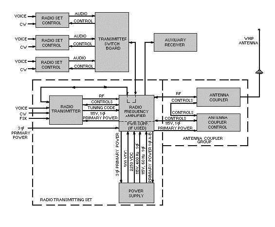
Figure 3-9.—Typical radio transmitting set block diagram.
RECEIVERS
The receiver we will discuss is a triple-conversion superheterodyne, tunable from 2 to 30 megahertz.
Triple conversion uses three IF frequencies to give better adjacent-channel selectivity and greater image-
frequency suppression. Figure 3-10 shows the front panel of this receiver where tuning is done digitally
by five controls and a switch. A display window directly above each control provides a digital readout of
the frequency setting. The displayed frequency can be changed in 1-kilohertz increments. The front panel
switch allows the operating frequency to be changed in 100- or 500-hertz increments depending on the
model. This will provide you with 280,000 discrete frequencies locked to a very accurate frequency
standard. You can continuously tune each 1,000-hertz increment by selecting the VERNIER position of
the hertz switch. When using the vernier, the full accuracy of the frequency standard is sacrificed. The
receiver demodulates and provides audio outputs for the lsb, usb, isb, AM, cw, and fsk types of received
signals.