1-45
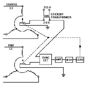
Figure 1-36.—Dual-speed synchro system using a stickoff transformer.
This voltage is normally about 2.5 volts and is commonly termed "stickoff" voltage. It is obtained
from the secondary of a small transformer. The voltage induced in the secondary of the transformer shifts
the 0º position of the coarse CT To reestablish a new 0º position, the stator of the coarse CT must be
turned through an angle that induces an opposing 2.5 volts in the rotor to cancel the stickoff voltage.
Therefore, at 0º the two voltages cancel and no input exists to drive the servo amplifier. Should the rotor
of the CT stop at 180º, the same 2.5 volts would be induced in the rotor. However, it would be in phase
with the stickoff voltage and no cancellation would occur. The end result is an error signal at 180º that
drives the dual-speed synchro system out of any false synchronizations.
TRI-SPEED SYNCHRO SYSTEM
The advent of long-range missiles and high-speed aircraft has brought about the need for accurately
transmitting very large quantities. This is best done by a tri-speed synchro system, which transmits data at
three different speeds. These speeds are sometimes referred to as coarse, medium or intermediate, and
fine. A typical weapons systems, for example, might transmit range in miles, thousands of yards, and
hundreds of yards. By providing this range in three different scales, greater accuracy is obtained than
would be possible with a dual-speed system. Representative speeds for tri-speed systems include 1, 36,
and 180; 1, 36, and 360; and 1, 18, and 648.
Q-53. What is the name given to the synchro system that transmits data at two different speeds?
Q-54. What is the main reason for using a multispeed synchro system instead of a single-speed synchro
system?
Q-55. In a dual-speed synchro system what determines the two specific speeds at which the data will be
transmitted?
Q-56. What type of synchro system is used to transmit very large quantities?


