1-40
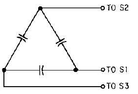
Figure 1-29.—The synchro capacitor.
The three delta-connected capacitors, shown in figure 1-29, usually come as a unit mounted in a case
with three external connections. The entire unit is called a SYNCHRO CAPACITOR. The synchro
capacitor is made in many sizes to meet the requirements of all sizes of standard differentials and control
transformers. The synchro capacitor is rated by its total capacity, which is the sum of the individual
capacities in the unit.
Figure 1-30 shows how a synchro capacitor affects the operation of a control synchro system. In this
figure, the capacitor is placed between the CX and the CT. Two current meters are also placed in the
circuit to show the effect the capacitor has on stator current. The meter connected between the capacitor
and the CT reads normal stator current, 32 milliamperes (mA). This current would normally flow in the
stator of the CX if the synchro capacitor were not connected. The other meter reads 10 mA, which is what
is left of the original stator current after the magnetizing current has been canceled by the synchro
capacitor. By reducing the current drain on the transmitter, the sensitivity and accuracy of the system
increase.
Figure 1-30.—The use of a synchro capacitor with a CT.
Figure 1-31 shows another application of a synchro capacitor; this time in a differential system in
this circuit the capacitor is placed between a TX and a TDX. The meter readings show the same
comparison between currents as in the previous paragraph. The only significant difference between this
circuit and the one in figure 1-30 is that the differential draws more stator current than the CT.


