1-38
When the rotor of the CX in view A of figure 1-27 is turned 60º clockwise, the magnetic field in the
CX (black arrow) and the magnetic field in the CT (white arrow) also rotate 60º clockwise. This action
induces a voltage in the CT rotor that is in phase with the ac supply, as indicated by the oscilloscope
presentation. If the rotor of the CX in view B is turned 60º in a counterclockwise direction from its 0º
position, the magnetic field (white arrow) in the CT also rotates counterclockwise through the same
number of degrees as the CX. Since the magnetic field in the stator of the CT cuts through the rotor in the
opposite direction, the induced voltage in the rotor is now out of phase with the ac supply to the CX, as
shown in the oscilloscope presentation.
At times it is necessary, because the CT is used to control servo systems, to have the CT output
reduced to zero volts to prevent any further movement of a load. To accomplish this, it is necessary to
turn the rotor of the CT through the same number of degrees and in the same direction as the rotor of the
CX. This places the CT rotor perpendicular to its own stator field and reduces its output to zero volts as
illustrated in view C.
The CT output voltage discussed throughout this section is commonly referred to as an ERROR
SIGNAL. This is because the voltage represents the amount and direction that the CX and CT rotors are
out of correspondence. It is this error signal that eventually is used in moving the load in a typical servo
system.
Now that we have covered the basic operation of the control synchro system, let us see how this
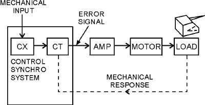
system works with a servo system to move heavy equipment. Figure 1-28 shows a block diagram of a
typical servo system that uses a control synchro system. Assume the shaft of the CX in this system is
turned by some mechanical input. This causes an error signal to be generated by the CT because the CX
and the CT rotors are now out of correspondence. The error signal is amplified by the servoamplifier and
applied to the servomotor. The servomotor turns the load, and through a mechanical linkage called
RESPONSE, also turns the rotor of the CT. The servomotor turns the rotor of the CT so that it is once
again in correspondence with the rotor of the CX, the error signal drops to zero volts, and the system
comes to a stop.
Figure 1-28.—A positioning servo system using a control synchro system.
Q-44. When a CT is on electrical zero, what is the relationship between its rotor and the S2 winding?
Q-45. What is the amplitude and voltage induced into the rotor when the CX is turned 90º while the CT
remains on electrical zero?
Q-46. What is the name given to the electrical output of a CT?
Q-47. In a control synchro system, when is the output of the CT reduced to zero?


