1-48
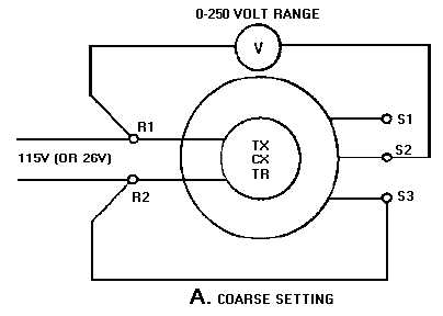
Figure 1-38A.—Zeroing a transmitter or receiver by the voltmeter method.
3. Energize the synchro circuit and turn the stator until the meter reads about 37 volts (15 volts for a
26-volt synchro). Should the voltmeter read approximately 193 volts (115 volts + 78 volts = 193
volts), the rotor is at 180º. Turn it through a half revolution to bring it back to 0º. If you cannot
obtain the desired 37 (or 15) volts, use the lowest reading you can take with the meter. This is the
coarse setting and places the synchro approximately on electrical zero.
4. Deenergize the synchro circuit and connect the meter as shown in view B. Start with a high scale
on the meter and work down to the 0- to 5-volt scale to protect the meter movement.
Figure 1-38B.—Zeroing a transmitter or receiver by the voltmeter method.
5. Reenergize the synchro circuit and adjust the stator for a zero or minimum voltage reading. This
is the fine electrical zero position of the synchro.
When you have reconnected a TX and a TR into a system after zeroing them, you can perform a
simple check on the system to see if they are accurately on electrical zero. First, place the transmitter on
0º. When the system reaches the point of correspondence, the induced voltages in the S1 and S3 stator
windings of both synchros should be equal. Since the terminals of S1 and S3 are at equal potential, a


