3-24
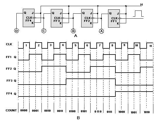
Figure 3-23. —Four-stage ripple counter: A. Logic diagram; B. Timing diagram.
Assume that A, B, C, and D are lamps and that all the FFs are reset. The lamps will all be out, and
the count indicated will be 00002. The negative-going pulse of clock pulse 1 causes FF1 to set. This lights
lamp A, and we have a count of 00012. The negative-going pulse of clock pulse 2 toggles FF1, causing it
to reset. This negative-going input to FF2 causes it to set and causes B to light. The count after two clock
pulses is 00102, or 210. Clock pulse 3 causes FF1 to set and lights lamp A. The setting of FF1 does not
affect FF2, and lamp B stays lit. After three clock pulses, the indicated count is 00112.
Clock pulse 4 causes FF1 to reset, which causes FF2 to reset, which causes FF3 to set, giving us a
count of 01002. This step shows the ripple effect.
This setting and resetting of the FFs will continue until all the FFs are set and all the lamps are lit. At
that time the count will be 11112 or 1510. Clock pulse 16 will cause FF1 to reset and lamp A to go out.
This will cause FF2 through FF4 to reset, in order, and will extinguish lamps B, C, and D. The counter
would then start at 00012 on clock pulse 17. To display a count of 1610 or 100002, we would need to add
another FF.
The ripple counter is also called an ASYNCHRONOUS counter. Asynchronous means that the
events (setting and resetting of FFs) occur one after the other rather than all at once. Because the ripple
count is asynchronous, it can produce erroneous indications when the clock speed is high. A high-speed
clock can cause the lower stage FFs to change state before the upper stages have reacted to the previous
clock pulse. The errors are produced by the FFs’ inability to keep up with the clock.


