3-20
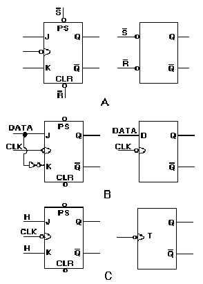
Figure 3-19. —J-K versatility: A. Using just the PS and CLR inputs; B. Data applied to the J input; C. Both J and K
inputs held HIGH.
In view A, using just the PS and CLR inputs of the J-K will cause it to react like an R-S FF.
In view B, data is applied to the J input. This same data is applied to the K input through an inverter
to ensure that the K input is in the opposite state. In this configuration, the J-K performs the same
function as a D FF.
View C shows both the J and K inputs held at 1, or HIGH. The FF will change state or toggle with
each negative-going transition of the clock just as a T FF will.
Now you can see the versatility of the J-K FF.
Q27. What type of FF can be used as an R-S, a T, or a D FF?
Q28. What will be the output of Q if J is HIGH, PS and CLR are HIGH, and the clock is going
negative?
Q29. Assume that K goes HIGH and J goes LOW; when will the FF reset?
Q30. What logic levels must exist for the FF to be toggled by the clock?
Q31. What two inputs to a J-K FF will override the other inputs?
Q32. How is the J-K FF affected if PS and CLR are both LOW?


