3-31
On the negative-going signal of CP8, all FFs are set, and all the lamps are lighted. The CLK pulse
toggles FF1, making output Q go HIGH. As output Q goes LOW, the negative-going signal causes FF2
to toggle. As FF2, output Q, goes HIGH, output Q goes LOW, causing FF3 to toggle and set. As each FF
sets, its indicator lamp lights. The counter is now ready to again start counting down from 1112 with the
next CLK pulse.
Q49. How many FFs are required to count down from 1510?
Q50. What signal causes FF2 to toggle?
REGISTERS
A register is a temporary storage device. Registers are used to store data, memory addresses, and
operation codes. Registers are normally referred to by the number of stages they contain or by the number
of bits they will store. For instance, an eight-stage register would be called an 8-bit register. The contents
of the register is also called a WORD. The contents of an 8-bit register is an 8-bit word. The contents of a
4-bit register is a 4-bit word and so forth.
Registers are also used in the transfer of data to and from input and output devices such as teletypes,
printers, and cathode-ray tubes.
Most registers are constructed of FFs and associated circuitry. They permit us to load or store data
and to transfer the data at the proper time.
PARALLEL REGISTERS
Parallel registers are designed to receive or transfer all bits of data or information simultaneously.
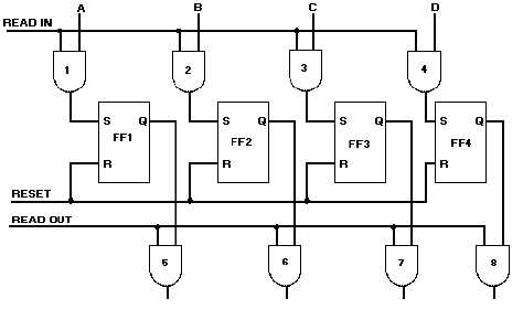
A 4-bit parallel register is shown in figure 3-28. The data inputs are A, B, C, and D. The FFs store
the data until it is needed. AND gates 5, 6, 7, and 8 are the transfer gates.
Figure 3-28. —Four-bit parallel register.


