2-20
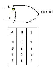
Figure 2-20. —OR gate with one inverted input.
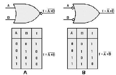
Figure 2-21compares a NOR gate (view A), to an OR gate with inverters on both inputs (view B),
and shows the respective Truth Tables. The NOR gate will produce a HIGH output only when both inputs
are LOW. The OR gate with inverted inputs produces a HIGH output with all input combinations
EXCEPT when both inputs are HIGH. This figure also illustrates the differences between the expressions
f = A
B
+
(A OR B quantity NOT) and f = A + B (NOT A OR NOT B).
Figure 2-21. —Comparison of NOR gate and OR gate with inverted inputs: A. NOR gate; B. OR gate with inverters on
both inputs.
As with the NAND gate, one or more inputs to NOR gates may be inverted. Figure 2-22 shows the
result of inverting a NOR gate input. In this case, because of the inversion of the B input and the inversion
of the output, the only time this gate will produce a HIGH output is when A is LOW and B is HIGH. The
output Boolean expression for this gate is f =
B
A +
, spoken “A OR NOT B quantity NOT.”


