2-18
Up to now you have seen inverters used alone or on the output of AND and OR gates. Inverters may
also be used on one or more of the inputs to the logic gates. Take a look at the examples as discussed in
the following paragraphs.
AND/NAND GATE VARIATIONS
If we place an inverter on one input of a two-input AND gate, the output will be quite different from
that of the standard AND gate.
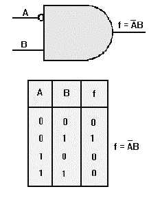
In figure 2-17, we have placed an inverter on the A input. When A is HIGH, the inverter makes it a
LOW going into the AND gate. In order for the output to be HIGH, A would have to be LOW while B is
HIGH, as shown in the Truth Table. If the inverter were on the B input, the output expression would then
be f = A B .
Figure 2-17. —AND gate with one inverted input.
Now let’s compare a NAND gate to an AND gate with an inverter on each input. Figure 2-18 shows
these gates and the associated Truth Tables. With the NAND gate (view A), the output is HIGH when
either or both inputs is/are LOW. The AND gate with inverters on each input (view B), produces a HIGH
output only when both inputs are LOW. This comparison also points out the differences between the
expressions f = A B (A AND B quantity NOT) and f =
A B (NOT A AND NOT B).
Now, look over the Truth Tables for figures 2-17, 2-18, and 2-19; look at how the outputs vary with
inverters in different positions.