2-19
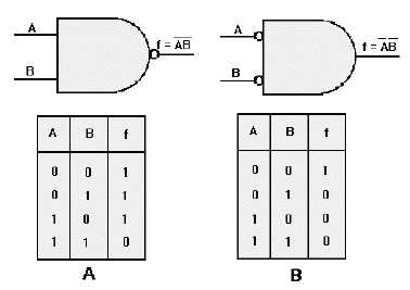
Figure 2-18. —Comparison of NAND gate and AND gate with inverted inputs: A. NAND gate; B. AND gate with inverters
on each input.
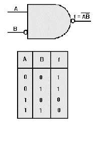
Figure 2-19. —NAND gate with one inverted input.
OR/NOR GATE VARIATIONS
The outputs of OR and NOR gates may also be changed with the use of inverters.
An OR gate with one input inverted is shown in figure 2-20. The output of this OR gate requires that
A be LOW, B be HIGH, or both of these conditions existing at the same time in order to have a HIGH
output. Since the A input is inverted, it must be LOW if B is LOW in order to produce a HIGH output.
Therefore the output is f = A +B.


