2-20
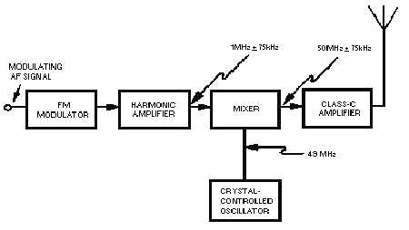
stability of the unmodulated 50-megahertz carrier would be 50 times better than that which harmonic
multiplication could provide.
Figure 2-14.—Method for improving frequency stability of fm system.
Varactor FM Modulator.—Another fm modulator which is widely used in transistorized circuitry
uses a voltage-variable capacitor (VARACTOR). The varactor is simply a diode, or pn junction, that is
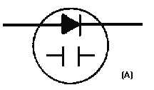
designed to have a certain amount of capacitance between junctions. View (A) of figure 2-15 shows the
varactor schematic symbol. A diagram of a varactor in a simple oscillator circuit is shown in view (B).
This is not a working circuit, but merely a simplified illustration. The capacitance of a varactor, as with
regular capacitors, is determined by the area of the capacitor plates and the distance between the plates.
The depletion region in the varactor is the dielectric and is located between the p and n elements, which
serve as the plates. Capacitance is varied in the varactor by varying the reverse bias which controls the
thickness of the depletion region. The varactor is so designed that the change in capacitance is linear with
the change in the applied voltage. This is a special design characteristic of the varactor diode. The
varactor must not be forward biased because it cannot tolerate much current flow. Proper circuit design
prevents the application of forward bias.
Figure 2-15A.—Varactor symbol and schematic. SCHEMATIC SYMBOL.


