2-26
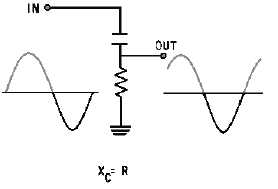
Figure 2-22.—Phase shifting a sine wave.
The capacitor in series with the resistor forms a phase-shift circuit. With a constant frequency rf
carrier applied at the input, the output across the resistor would be 45 degrees out of phase with the input
if X
C
= R.
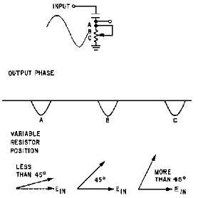
Now, let’s vary the resistance and observe how the output is affected in figure 2-23. As the resistance
reaches a value greater than 10 times XC, the phase difference between input and output is nearly 0
degrees. For all practical purposes, the circuit is resistive. As the resistance is decreased to 1/10 the value
of X
C, the phase difference approaches 90 degrees. The circuit is now almost completely capacitive. By
replacing the resistor with a vacuum tube, as shown in view (A) of figure 2-24, we can vary the resistance
(vacuum-tube impedance) by varying the voltage applied to the grid of the tube. The frequency applied to
the circuit (from a crystal-controlled master oscillator) will be shifted in phase by 45 degrees with no
audio input [view (B)]. With the application of an audio signal, the phase will shift as the impedance of
the tube is varied.
Figure 2-23.—Control over the amount of phase shift.


