1-30
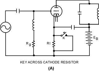
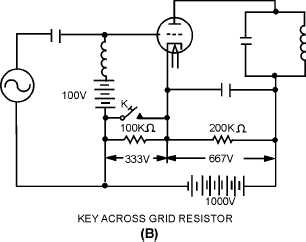
BLOCKED-GRID KEYING.—Two methods of BLOCKED-GRID KEYING are shown in figure
1-24. The key in view (A) shorts cathode resistor R1 allowing normal plate current to flow. With the key
open, reduced plate current flows up through resistor R1 making the end connected to grid resistor Rg
negative. If R1 has a high enough value, the bias developed is sufficient to cause cutoff of plate current.
Depressing the key short-circuits R1. This increases the bias above cutoff and allows the normal flow of
plate current. Grid resistor Rg is the usual grid-leak resistor for normal biasing.
Figure 1-24A.—Blocked-grid keying.
Figure 1-24B.—Blocked-grid keying.
The blocked-grid keying method in view (B) affords a complete cutoff of plate current. It is one of
the best methods for keying amplifier stages in transmitters. In the voltage divider with the key open, two-
thirds of 1,000 volts, or 667 volts, is developed across the 200-kilohm resistor; one-third of 1,000 volts, or
333 volts, is developed across the 100-kilohm resistor. The grid bias is the sum of 100 volts and 333
volts, or 433 volts. This sum is below cutoff and no plate current flows. The plate voltage is 667 volts.
With the key closed, the 200-kilohm resistor drops 1,000 volts. The plate voltage becomes 1,000 volts at
the same time the grid bias becomes 100 volts. Grid bias is reduced enough so that the triode amplifier
will conduct only on the peaks of the drive signal.


