1-35
frequency. A second advantage is that the rf power amplifier is operated so that a small change in the
voltage applied to its grid circuit will produce a large change in the power developed in its plate circuit.
Rf power amplifiers require that a specific amount of power be fed into the grid circuit. Only in this
way can the tube deliver an amplified power output. However, the stable oscillator can produce only
limited amounts of power. Therefore, the mopa transmitter is limited in the amount of power it can
develop. This is one of the disadvantages of the mopa transmitter. Another disadvantage is that it often is
impractical for use at very- and ultra-high frequencies. The reason is that the stability of self-excited
oscillators decreases rapidly as the operating frequency increases. Circuit tuning capacitances are small at
high frequencies and stray capacitances adversely affect frequency stability.
MULTISTAGE HIGH-POWER TRANSMITTERS.—The power amplifier of a high-power
transmitter may require far more driving power than can be supplied by an oscillator. Therefore, one or
more low-power intermediate amplifiers may be inserted between the oscillator and the final power
amplifier to boost power to the antenna. In some types of equipment, a VOLTAGE AMPLIFIER, called a
BUFFER is used between the oscillator and the first intermediate amplifier. The ideal buffer is operated
class A and is biased negatively to prevent grid current flow during the excitation cycle. Therefore, it does
not require driving power from, nor does it load down, the oscillator. The purpose of the buffer is to
isolate the oscillator from the following stages and to minimize changes in oscillator frequency that occur
with changes in loading. A buffer is required when keying takes place in an intermediate or final amplifier
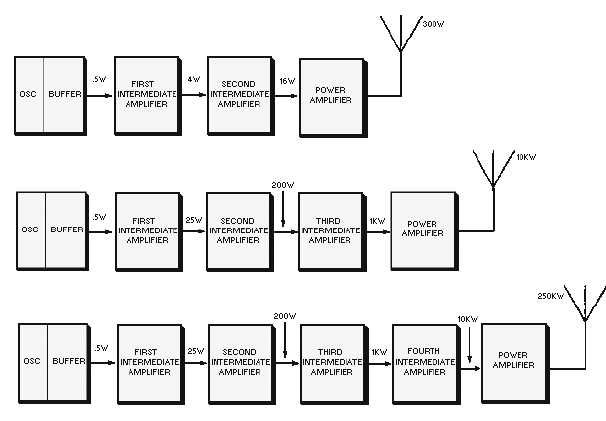
operating at comparatively high power. Look at the block diagrams of several medium-frequency
transmitters in figure 1-30. The input and output powers are given for each stage. You should be able to
see that the power output rating of a transmitter can be increased by adding amplifier tubes capable of
delivering the power required.
Figure 1-30.—Block diagram of several medium-frequency transmitters.


