1-33
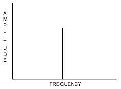
analysis (figure 1-27) illustrates the transmitted frequency characteristics of a cw signal. Because the cw
signal is a pure sine wave, it occupies only a single frequency in the rf spectrum and the system is
relatively simple.
Figure 1-27.—Carrier-wave signal spectrum analysis.
Q-18. What is amplitude modulation?
Q-19. What are the three requirements for cw transmission?
Q-20. Name two methods of oscillator keying.
Q-21. State the method used to increase the speed of keying in a cw transmitter.
Q-22. Name three advantages of cw transmission.
Single-Stage Transmitters
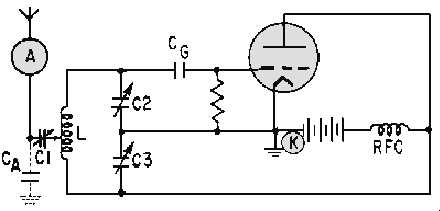
A simple, single-tube cw transmitter can be made by coupling the output of an oscillator directly to
an antenna (figure 1-28). The primary purpose of the oscillator is to develop an rf voltage which has a
constant frequency and is immune to outside factors which may cause its frequency to shift. The output of
this simple transmitter is controlled by placing a telegraph key at point K in series with the voltage
supply. Since the plate supply is interrupted when the key is open, the circuit oscillates only as long as the
key is closed. Although the transmitter shown uses a Colpitts oscillator, any of the oscillators previously
described in NEETS, Module 9, Introduction to Wave-Generation and Wave-Shaping Circuits can be
used.
Figure 1-28.—Simple electron-tube transmitter.


