2-33
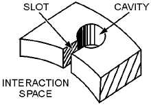
Figure 2-29A.—Equivalent circuit of a hole-and-slot cavity.
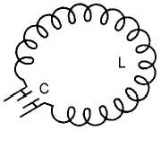
Figure 2-29B.—Equivalent circuit of a hole-and-slot cavity.
Electrical Equivalent.—Notice in figure 2-29A, that the cavity consists of a cylindrical hole in the
copper anode and a slot which connects the cavity to the interaction space.
The equivalent electrical circuit of the hole and slot is shown in figure 2-29B. The parallel sides of
the slot form the plates of a capacitor while the walls of the hole act as an inductor. The hole and slot thus
form a high-Q, resonant LC circuit. As shown in figure 2-27, the anode of a magnetron has a number of
these cavities.
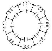
An analysis of the anodes in the hole-and-slot block reveals that the LC tanks of each cavity are in
series (assuming the straps have been removed), as shown in figure 2-30. However, an analysis of the
anode block after alternate segments have been strapped reveals that the cavities are connected in parallel
because of the strapping. Figure 2-31 shows the equivalent circuit of a strapped anode.
Figure 2-30.—Cavities connected in series.


