1-8
NOTE
This method of labeling waveguides is not standard in all texts. Different methods may be used in
other texts on microwave principles, but this method is in accordance with Navy Military Standards
(MIL-STDS).
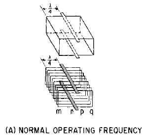
The ability of a waveguide of a given dimension to transport more than one frequency may be better
understood by analyzing the actions illustrated in figure 1-10A, B, and C. A waveguide may be
considered as having upper and lower quarter-wave sections and a central section which is a solid
conductor called a BUS BAR. In figure 1-10A, distance mn is equal to distance pq, and both are equal to
one quarter-wavelength (!/4).
Figure 1-10A.—Frequency effects on a waveguide. NORMAL OPERATING FREQUENCY.
NOTE
Throughout NEETS, 1/4! and !/4 are both used to represent one quarter-wavelength and are used
interchangeably. Also, !/2 and 3/2! will be used to represent one half-wavelength and 1 1/2 wavelengths,
respectively.
Distance np is the width of the bus bar. If the overall dimensions of the waveguide are held constant,
the required length of the quarter-wave sections DECREASES as the frequency increases. As illustrated
in figure 1-10B, this causes the width of the bus bar to INCREASE. In theory the waveguide could
function at an infinite number of frequencies higher than the designed frequency; as the length of each
quarter-wave section approaches zero, the bus bar continues to widen to fill the available space. However,
in practice, an upper frequency limit is caused by modes of operation, which will be discussed later.


