1-6
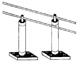
Figure 1-5.—Two-wire transmission line using ordinary insulators.
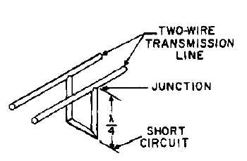
Figure 1-6.—Quarter-wave section of transmission line shorted at one end.
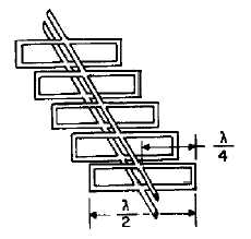
Figure 1-7 shows several metallic insulators on each side of a two-wire transmission line. As more
insulators are added, each section makes contact with the next, and a rectangular waveguide is formed.
The lines become part of the walls of the waveguide, as illustrated in figure 1-8. The energy is then
conducted within the hollow waveguide instead of along the two-wire transmission line.
Figure 1-7.—Metallic insulators on each side of a two-wire line.