1-21
frequency selection to be accomplished in a different manner. It gives the circuit different characteristics.
The first of these characteristics is the ability to store energy.
The Characteristics of a Typical Parallel-Resonant Circuit
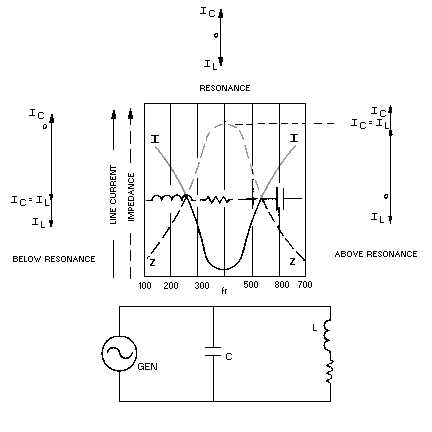
Look at figure 1-11. In this circuit, as in other parallel circuits, the voltage is the same across the
inductor and capacitor. The currents through the components vary inversely with their reactances in
accordance with Ohm's law. The total current drawn by the circuit is the vector sum of the two individual
component currents. Finally, these two currents, IL and IC, are 180 degrees out of phase because the
effects of L and C are opposite. There is not a single fact new to you in the above. It is all based on what
you have learned previously about parallel a.c. circuits that contain L and C.
Figure 1-11.—Curves of impedance and current in an RLC parallel-resonant circuit.
Now, at resonance, XL is still equal to X
C. Therefore, IL must equal IC. Remember, the voltage is the
same; the reactances are equal; therefore, according to Ohm's law, the currents must be equal. But, don't
forget, even though the currents are equal, they are still opposites. That is, if the current is flowing "up" in
the capacitor, it is flowing "down" in the coil, and vice versa. In effect, while the one component draws
current, the other returns it to the source. The net effect of this "give and take action" is that zero current
is drawn from the source at resonance. The two currents yield a total current of zero amperes because they
are exactly equal and opposite at resonance.
A circuit that is completed and has a voltage applied, but has zero current, must have an INFINITE
IMPEDANCE (apply Ohm's law — any voltage divided by zero yields infinity).


