9
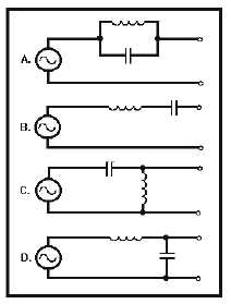
Figure 1G.—Filter circuits.
TO ANSWER QUESTIONS 1-53 AND 1-54,
SELECT FROM FIGURE 1G THE CIRCUIT
DIAGRAM WHICH MATCHES THE
CIRCUIT NAME IN EACH QUESTION.
CHOICES IN THE FIGURE MAY BE USED
ONCE, MORE THAN ONCE, OR NOT AT
ALL.
1-53. Band-reject filter.
1. A
2. B
3. C
4. D
1-54. High-pass filter.
1. A
2. B
3. C
4. D
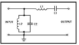
Figure 1H.—Filter circuit.
IN ANSWERING QUESTIONS 1-55 AND
1-56, REFER TO THE CIRCUIT IN FIGURE
1H.
1-55. L1 and C1 in the circuit offer what type
of opposition to (a) frequencies near
resonance and (b) all other frequencies?
1. (a) Minimum
(b) minimum
2. (a) Minimum
(b) maximum
3. (a) Maximum
(b) maximum
4. (a) Maximum
(b) minimum
1-56. In the type of filter circuit in the figure,
what is/are the "cutoff point(s)?"
1. Upper frequency limit only
2. Lower frequency limit only
3. Both upper and lower frequency
limits
1-57. In a series-resonant circuit that is
operating at resonance, what is the
amplitude of the applied voltage
compared to (a) inductor voltage and
(b) capacitor voltage?
1. (a) Lower
(b) lower
2. (a) Lower
(b) higher
3. (a) Higher
(b) higher
4. (a) Higher
(b) lower


