3-18
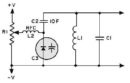
Figure 3-16.—Varactor tuned resonant circuit.
Figure 3-16 shows a dc voltage felt at the wiper of potentiometer R1 which can be adjusted between
+V and
-
V. The dc voltage, passed through the low resistance of radio frequency choke L2, acts to
reverse bias varactor diode C3. The capacitance of C3 is in series with C2, and the equivalent capacitance
of C2 and C3 is in parallel with tank circuit L1-C1. Therefore, any variation in the dc voltage at R1 will
vary both the capacitance of C3 and the resonant frequency of the tank circuit. The radio-frequency choke
provides high inductive reactance at the tank frequency to prevent tank loading by R1. C2 acts to block dc
from the tank as well as to fix the tuning range of C3.
An ohmmeter can be used to check a varactor diode in a circuit. A high reverse-bias resistance and a
low forward-bias resistance with a 10 to 1 ratio in reverse-bias to forward-bias resistance is considered
normal.
Q7. What is the main difference in construction between normal PN junction diodes and tunnel
diodes?
Q8. What resistance property is found in tunnel diodes but not in normal diodes?
Q9. When compared to the ordinary diode, the tunnel diode has what type of depletion region?
Q10. In the tunnel diode, the tunneling current is at what level when the forbidden gap of the N-type
material is at the same energy level as the empty states of the P-type material?
Q11. The varactor displays what useful electrical property?
Q12. When a PN junction is forward biased, what happens to the depletion region?
Q13. When the reverse bias on a varactor is increased, what happens to the effective capacitance?
Silicon Controlled Rectifier (SCR)
The SILICON CONTROLLED RECTIFIER, usually referred to as an SCR, is one of the family of
semiconductors that includes transistors and diodes. A drawing of an SCR and its schematic
representation is shown in views A and B of figure 3-17. Not all SCRs use the casing shown, but this is
typical of most of the high-power units.


